The Evolution of Powertrain Microcontrollers and its Impact on Development Processes and Tools, Part 1

As the new generation of RISC powertrain MCUs propagate through the automotive development cycle, there will likely be more difficulty in debugging the ECU reliably and efficiently. Simply stated, there is less support for the development process in the new high-performance single-chip RISC MCUs, which could create critical and costly delays in the development cycle. Additionally, as powertrain MCUs continue to evolve, superscalar or multiple-issue RISC implementations may be used as the central processor. With the capability to issue multiple instructions in one clock cycle, this will only magnify the development support problem. Thus it is essential to address this impending problem with a strategy that both automotive and tools developers can agree. A strategy for development standards is presented in this paper, and a new powertrain MCU development interface standard is proposed.
•Evolution of Powertrain Microcontrollers
•Impact on SW/HW Development
•Impact on Calibration
•Calibration Performed with External to MCU Memory Emulation
Evolution of Powertrain Microcontrollers
With the advent of the new 32-bit powertrain MCUs driven by high performance, integration and low cost, there are unique challenges and trade-offs for both SW/HW development engineers and development tools vendors. Ever increasing performance needs have led to the migration to RISC processors with on-chip instruction and data caches, or high-speed RAM and Flash, to meet the high memory bandwidth requirements of these architectures. High frequency one clock cycle instruction and data buses are on-chip to support the memory bandwidth requirements to the internal memory system.
The challenges offered with the emergence of the new 32-bit MCUs are to provide the visibility needed for logic analyzer, processor emulation and calibration systems, while not compromising performance and cost saving features. The new MCUs solve this problem by providing trade-offs to the SW/HW development engineers. Development engineers can choose from a number of options which provide an increasing level of visibility, but with an impact of a reduction in performance and features. Consequently, there is no standard approach used since each is customized to the user's own preferences and needs. This presents a compatibility challenge to development tools vendors.
The integration of high-speed RAM and flash onto the powertrain MCU creates a paradigm shift for processor run control and logic analysis tools. With high-speed memory on-chip, memory substitution techniques may no longer be truly transparent due to the significant latency increase in accessing off-chip memory relative to on-chip memory. Thus comprehensive emulator techniques become problematic for doing run control operations without impacting the customer's system e.g. reading and writing memory and internal registers, and halting and running the microprocessor. Additionally, since accesses to internal memory do not, by default, show up on external pins, there is insufficient visibility for logic analysis. With integrated memory, there is an expectation by automotive developers that some applications will not require the external address and data signals. For these applications, a cost-saving technique is to use these pins for general-purpose I/O. Run control and logic analysis issues are further complicated by removal of the external address and data signals altogether. As a result of the powertrain MCU evolution, tools vendors must re-approach their solution technology in new and cooperative ways with the silicon vendors.
ECU calibration comprises data acquisition of intermediate calculated variables, co-processing or analysis of critical parametrics, and tuning of calibration constants either on a dynamometer or in-vehicle. In today's powertrain MCUs, where RAM and flash are easily accessible, the calibration process is essentially non-obtrusive.
But with high-speed on-chip memory and the removal of the external address and data signals altogether, calibration issues may impact both the SW/HW developer and the calibrator. Depending upon the method used for acquiring variables and updating constants, there can be a range of impacts on MCU overhead. The developer must trade-off options which provide an increasing level of acquisition and tuning capability, but with an impact of a reduction in performance and features.
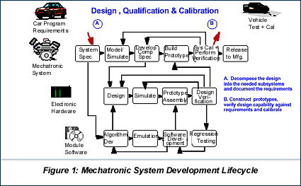
Figure 1 illustrates at a high level view the automotive development process steps for a mechatronic-based system. This diagram identifies the three major sub-systems being developed and the associated steps encountered in each sub-system's development. The diagram is also useful in demonstrating the expansiveness and complexity of the automotive development process, and how different skills and organizations are involved. Requirements are initially extracted from the vehicle level to powertrain needs, then to electronic hardware, and finally to module software. As the design sub-systems come together into prototypes, they are then qualified and calibrated to verify conformance with the initial requirements.
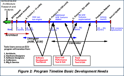
Figure 2 illustrates the timeline and steps associated with a typical powertrain program. Across the program timeline the design content evolves to become more complete as the developers and tools change.
Automotive developers have certain needs of their development tools in order to accomplish their jobs. For logic analysis the basic needs are:
For run control the basic needs are:
Note that the capability for run control, logic analysis and memory overlay or substitution comprise what is traditionally known as processor or in-circuit emulation.
For calibration the basic needs are:
For algorithm development the basic need is to rapidly prototype new ECU algorithms and perform conformance testing in a vehicle e.g. new fuel strategy such as direct injection. The new algorithm is typically implemented in a special emulation module which is connected to the ECU and acts as a co-processor.
Control strategy SW is modified to make a procedure call to the special emulation module at the appropriate time, and after waiting for result calculations, the SW proceeds with normal control strategy.
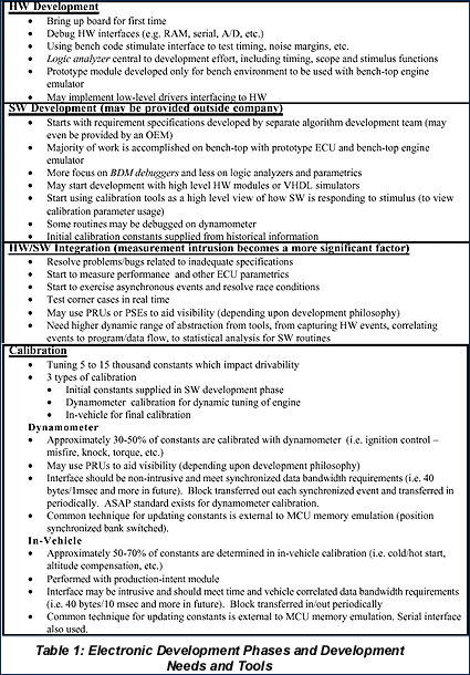
Table 1 describes the ECU development phases and further demarcates the development needs and tools which are used in each phase.
It should be noted that there are different philosophies with regard to ECU development for powertrain MCUs comprising fast on-chip instruction and data memories. One approach is to provide more MCU visibility to enhance the development process by using a Port Replacement Units (PRU) in module versions up through in-vehicle calibration. This adds risk since the PRU may be removed in the production module, which may impact ECU parametrics. Another approach is to transition to the production-intent module as early as possible in the development process. This approach provides lower risk but with potentially more difficulty during the development process. There are also varying approaches in between these two which trade-off the development process and risk.
Calibration Performed with External to MCU Memory Emulation
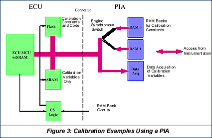
The predominant technique used today to perform calibration on the dynamometer and in-vehicle is with external to MCU memory emulation. A popular solution is Hewlett Packard's Parallel Interface Adapter (PIA) as shown in Figure 3. On the left side of Figure 3 you see the relevant pieces of the ECU, and on the right side the main building blocks of the PIA are shown.
When calibration is performed visibility is needed of intermediate calculated values (calibration variables) such as calculated ignition time, actual RPM, sensor temperatures, knock sensor value, etc., Many of these variables are calculated every cycle of each cylinder. The PIA provides instrumentation access to these variables through data acquisition hardware. By snooping the MCU's external bus for writes to calibration variables in the ECU SRAM, data acquisition hardware provides an image of the calibration variables for instrumentation access.
After parametric analysis is performed the two RAM banks of the PIA allow instrumentation to update calibration constants for ECU access. Chip select logic on the ECU is used to overlay flash memory containing calibration constants with new constants in RAM bank 0/1. So instead of reading calibration constants from the flash, the MCU reads them from one of the RAM banks. Which one of the banks calibration constants are read from is determined by a switch triggered by engine TDC occurrence. The position synchronous switch allows for coherent changes to calibration constants.


